Welcome to ZK Electronic
16 years of industry experience
Good material qualty, high efficiency, fast delivery
搜索
NEWS
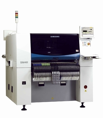
Methods to improve the placement efficiency of smt placement machine
- Categories:Industry News
- Author:Becky Su
- Origin:
- Time of issue:2023-12-02 10:54
- Views:
(Summary description)Methods to improve the placement efficiency of smt placement machine How to improve the placement speed of smt mounter, I believe that many smt industry friends have encountered such a problem. SMT machine is in the case of not causing any damage to the device and the base board, stable, fast, complete, correctly sucking the device, and quickly and accurately mount the device in the specified position, is now widely used in home appliances, communications, computers and other industries. SMT equipment in the purchase of the main considerations of its mounting accuracy and mounting speed, in the actual use of the process, in order to effectively improve product quality, reduce the cost of production in favor of improving production efficiency, then how to improve and maintain the SMT equipment mounting rate is the primary issue in front of the user. First: the meaning of the mounting rate Mounting rate refers to the actual number of devices mounted in a certain period of time and the ratio of the number of suction, that is: Mounting rate = × 100% Sucking number The total number of discarded pieces refers to the number of suction errors, the number of recognition errors, the number of standing pieces, the number of lost, and recognition errors and device specifications size error and device optical recognition of two kinds of bad. Mounter whether it is a small machine, medium-sized machine, large machine, whether it is a medium-speed machine, high-speed machine, they are mainly by the device storage and transportation devices, XY table, mounting head and control system components. The mounting head is the core and key components of the mounter, the mounting head generally has a fixed head and rotary head points, fixed general multi-head arrangement, as few as 1, as many as 8, can be taken at the same time or individually, the rotary head is divided into the horizontal plane rotation and rotation in the vertical plane. A: device suction Nozzle pickup height switching B: θI rotation (±90') C: Device optical recognition D: Device Attitude Detection θ2 rotation (±90') E: Mounting device/nozzle height switching F: θ3 rotation (±180'-θ) Nozzle home position detection of defective products elimination G: Nozzle switching H: Nozzle number detection According to the mounter from the pick and place the whole process, purely from the equipment side, in the correct setting of the nozzle pick height, picking up pieces of the center of the nozzle and the relative position of the feeder, the main factors affecting the placement rate of the device is to pick up pieces of the position, according to the equipment statistics of the production of information intelligence, and its impact accounts for the impact of the whole factor of more than 80%. And the causes are: on the one hand is the device storage and transportation device on the feeder, on the other hand is the suction nozzle, both in the feeder of the film about 60%, 40% or so is due to the suction nozzle pollution caused. Second, the impact of smt mounter feeder The impact of the feeder master concentrated in the feeder abnormal. Feeder drive motor drive, mechanical drive and cylinder drive and so on several kinds, here to mechanical drive as an example, explains the impact of the feeder on the mounting rate: 1: drive part wear Mechanical drive by the cam spindle drive feeding mechanism, quickly knocking to find the feeder to find the arm, through the connecting rod so that the ratchet connected to the components driven by the braided belt forward a distance, while driving the plastic tape disk will be braided on the plastic tape cap away from the suction nozzle down to complete the pickup action. However, due to the feeding mechanism of high-speed access to the feeder, after a long period of use, the feeder pawl wear and tear serious, resulting in the pawl can not drive the tape reel plastic tape normal peeling, so that the suction nozzle can not complete the work of taking pieces. Therefore, before installing the tape should carefully check the feeder, the pawl wheel has been worn feeder should be repaired immediately, can not be repaired should be replaced in a timely manner. 2:Feeder structure deformation Due to long-term use or improper operation of the operator, its pressure belt cover plate, thimble, spring and other movement mechanism to produce deformation, corrosion, etc., which leads to the device suction bias, standing piece or suction can not be devices, therefore, should be regularly inspected, found that the problem is handled in a timely manner, so as to avoid a large amount of waste of the device, and at the same time in the installation of a total of the feeder should be installed correctly and securely installed in the feeder section platform, especially without the height of the feeder detection of the device, or may result in the feeder or the feeder, or the feeder should be replaced immediately. Otherwise it may cause damage to the feede
Methods to improve the placement efficiency of smt placement machine
(Summary description)Methods to improve the placement efficiency of smt placement machine
How to improve the placement speed of smt mounter, I believe that many smt industry friends have encountered such a problem.
SMT machine is in the case of not causing any damage to the device and the base board, stable, fast, complete, correctly sucking the device, and quickly and accurately mount the device in the specified position, is now widely used in home appliances, communications, computers and other industries.
SMT equipment in the purchase of the main considerations of its mounting accuracy and mounting speed, in the actual use of the process, in order to effectively improve product quality, reduce the cost of production in favor of improving production efficiency, then how to improve and maintain the SMT equipment mounting rate is the primary issue in front of the user.
First: the meaning of the mounting rate
Mounting rate refers to the actual number of devices mounted in a certain period of time and the ratio of the number of suction, that is:
Mounting rate = × 100%
Sucking number
The total number of discarded pieces refers to the number of suction errors, the number of recognition errors, the number of standing pieces, the number of lost, and recognition errors and device specifications size error and device optical recognition of two kinds of bad.
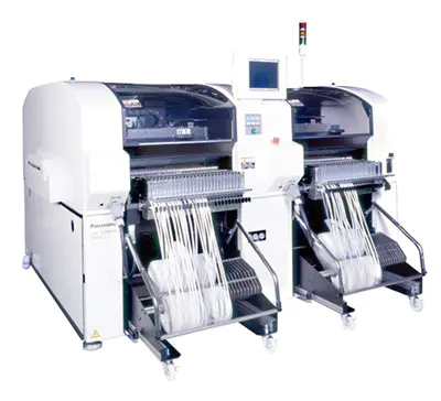
Mounter whether it is a small machine, medium-sized machine, large machine, whether it is a medium-speed machine, high-speed machine, they are mainly by the device storage and transportation devices, XY table, mounting head and control system components. The mounting head is the core and key components of the mounter, the mounting head generally has a fixed head and rotary head points, fixed general multi-head arrangement, as few as 1, as many as 8, can be taken at the same time or individually, the rotary head is divided into the horizontal plane rotation and rotation in the vertical plane.
A: device suction
Nozzle pickup height switching
B: θI rotation (±90')
C: Device optical recognition
D: Device Attitude Detection
θ2 rotation (±90')
E: Mounting device/nozzle height switching
F: θ3 rotation (±180'-θ)
Nozzle home position detection of defective products elimination
G: Nozzle switching
H: Nozzle number detection
According to the mounter from the pick and place the whole process, purely from the equipment side, in the correct setting of the nozzle pick height, picking up pieces of the center of the nozzle and the relative position of the feeder, the main factors affecting the placement rate of the device is to pick up pieces of the position, according to the equipment statistics of the production of information intelligence, and its impact accounts for the impact of the whole factor of more than 80%. And the causes are: on the one hand is the device storage and transportation device on the feeder, on the other hand is the suction nozzle, both in the feeder of the film about 60%, 40% or so is due to the suction nozzle pollution caused.
Second, the impact of smt mounter feeder
The impact of the feeder master concentrated in the feeder abnormal.
Feeder drive motor drive, mechanical drive and cylinder drive and so on several kinds, here to mechanical drive as an example, explains the impact of the feeder on the mounting rate:
1: drive part wear
Mechanical drive by the cam spindle drive feeding mechanism, quickly knocking to find the feeder to find the arm, through the connecting rod so that the ratchet connected to the components driven by the braided belt forward a distance, while driving the plastic tape disk will be braided on the plastic tape cap away from the suction nozzle down to complete the pickup action. However, due to the feeding mechanism of high-speed access to the feeder, after a long period of use, the feeder pawl wear and tear serious, resulting in the pawl can not drive the tape reel plastic tape normal peeling, so that the suction nozzle can not complete the work of taking pieces. Therefore, before installing the tape should carefully check the feeder, the pawl wheel has been worn feeder should be repaired immediately, can not be repaired should be replaced in a timely manner.
2:Feeder structure deformation
Due to long-term use or improper operation of the operator, its pressure belt cover plate, thimble, spring and other movement mechanism to produce deformation, corrosion, etc., which leads to the device suction bias, standing piece or suction can not be devices, therefore, should be regularly inspected, found that the problem is handled in a timely manner, so as to avoid a large amount of waste of the device, and at the same time in the installation of a total of the feeder should be installed correctly and securely installed in the feeder section platform, especially without the height of the feeder detection of the device, or may result in the feeder or the feeder, or the feeder should be replaced immediately. Otherwise it may cause damage to the feede
- Categories:Industry News
- Author:Becky Su
- Origin:
- Time of issue:2023-12-02 10:54
- Views:
Information
Methods to improve the placement efficiency of smt placement machine
How to improve the placement speed of smt mounter, I believe that many smt industry friends have encountered such a problem.
SMT machine is in the case of not causing any damage to the device and the base board, stable, fast, complete, correctly sucking the device, and quickly and accurately mount the device in the specified position, is now widely used in home appliances, communications, computers and other industries.
SMT equipment in the purchase of the main considerations of its mounting accuracy and mounting speed, in the actual use of the process, in order to effectively improve product quality, reduce the cost of production in favor of improving production efficiency, then how to improve and maintain the SMT equipment mounting rate is the primary issue in front of the user.
First: the meaning of the mounting rate
Mounting rate refers to the actual number of devices mounted in a certain period of time and the ratio of the number of suction, that is:
Mounting rate = × 100%
Sucking number
The total number of discarded pieces refers to the number of suction errors, the number of recognition errors, the number of standing pieces, the number of lost, and recognition errors and device specifications size error and device optical recognition of two kinds of bad.
Mounter whether it is a small machine, medium-sized machine, large machine, whether it is a medium-speed machine, high-speed machine, they are mainly by the device storage and transportation devices, XY table, mounting head and control system components. The mounting head is the core and key components of the mounter, the mounting head generally has a fixed head and rotary head points, fixed general multi-head arrangement, as few as 1, as many as 8, can be taken at the same time or individually, the rotary head is divided into the horizontal plane rotation and rotation in the vertical plane.
A: device suction
Nozzle pickup height switching
B: θI rotation (±90')
C: Device optical recognition
D: Device Attitude Detection
θ2 rotation (±90')
E: Mounting device/nozzle height switching
F: θ3 rotation (±180'-θ)
Nozzle home position detection of defective products elimination
G: Nozzle switching
H: Nozzle number detection
According to the mounter from the pick and place the whole process, purely from the equipment side, in the correct setting of the nozzle pick height, picking up pieces of the center of the nozzle and the relative position of the feeder, the main factors affecting the placement rate of the device is to pick up pieces of the position, according to the equipment statistics of the production of information intelligence, and its impact accounts for the impact of the whole factor of more than 80%. And the causes are: on the one hand is the device storage and transportation device on the feeder, on the other hand is the suction nozzle, both in the feeder of the film about 60%, 40% or so is due to the suction nozzle pollution caused.
Second, the impact of smt mounter feeder
The impact of the feeder master concentrated in the feeder abnormal.
Feeder drive motor drive, mechanical drive and cylinder drive and so on several kinds, here to mechanical drive as an example, explains the impact of the feeder on the mounting rate:
1: drive part wear
Mechanical drive by the cam spindle drive feeding mechanism, quickly knocking to find the feeder to find the arm, through the connecting rod so that the ratchet connected to the components driven by the braided belt forward a distance, while driving the plastic tape disk will be braided on the plastic tape cap away from the suction nozzle down to complete the pickup action. However, due to the feeding mechanism of high-speed access to the feeder, after a long period of use, the feeder pawl wear and tear serious, resulting in the pawl can not drive the tape reel plastic tape normal peeling, so that the suction nozzle can not complete the work of taking pieces. Therefore, before installing the tape should carefully check the feeder, the pawl wheel has been worn feeder should be repaired immediately, can not be repaired should be replaced in a timely manner.
2:Feeder structure deformation
Due to long-term use or improper operation of the operator, its pressure belt cover plate, thimble, spring and other movement mechanism to produce deformation, corrosion, etc., which leads to the device suction bias, standing piece or suction can not be devices, therefore, should be regularly inspected, found that the problem is handled in a timely manner, so as to avoid a large amount of waste of the device, and at the same time in the installation of a total of the feeder should be installed correctly and securely installed in the feeder section platform, especially without the height of the feeder detection of the device, or may result in the feeder or the feeder, or the feeder should be replaced immediately. Otherwise it may cause damage to the feeder or equipment.
3: poor lubrication of the feeder
General maintenance and maintenance of the feeder, it is easy to be ignored, but regular cleaning, washing, refueling lubrication is essential work.
Third, the influence of smt mounter suction nozzle
The suction nozzle is also another important factor affecting the mounting rate, caused by internal and external reasons.
1: internal reasons
On the one hand, the vacuum is not enough negative pressure, suction nozzle take pieces before the automatic conversion of the mechanical valve on the mounting head, by blowing gas conversion for the real it adsorption, resulting in a certain amount of negative pressure, when sucking up the parts, negative pressure sensor detects the value of a certain range of normal machines, and vice versa, suction with bad. Generally in the pick and place to mount the negative pressure at the suction nozzle should be at least 400mmHg or more, when mounting large devices negative pressure should be more than 70mmHg, so the vacuum pump should be cleaned regularly within the filter to ensure sufficient negative pressure; at the same time should be regularly checked the negative pressure detection sensor work status. On the other hand, the filter on the mounting head and the filter on the suction nozzle are blackened due to the surrounding environment or the impurity of the gas source being contaminated and clogged. Therefore, the filter should be replaced regularly, generally the filter on the nozzle should be replaced at least once every half a month, and the filter on the mounting head should be replaced at least once every half a year to ensure smooth airflow.
2: External causes
On the one hand, the air source circuit pressure relief, such as rubber hose aging, rupture, aging seals, wear and tear as well as wear and tear of the suction nozzle after a long period of time, on the other hand, due to the dust in the adhesive or the external environment, especially the paper tape packaging components in the cut off of a large number of waste debris, resulting in suction nozzle plugging, therefore, due to the daily inspection of the suction nozzle of the cleanliness of the suction nozzle, at any time to monitor the suction nozzle of the pick-up situation, the clogging or picking up bad nozzles should be timely cleaning or replacement of the suction nozzle. The nozzle should be cleaned or replaced in time to ensure a good condition. Meanwhile, when installing the nozzle, it is necessary to ensure a correct and firm installation, otherwise it will cause damage to the nozzle or the equipment.
Four: smt mounter device detection system
Device detection system is the necessary guarantee of placement accuracy and placement correctness. Divided into device optical recognition system and device attitude detection.
1: optical recognition system is a fixed installation of an optical camera system, it is in the mounting head of the rotating process by the camera to identify the shape of the component profile and thus optical imaging, and at the same time relative to the center of the device camera position and the rotation angle measurement and recorded, passed to the transmission control system, so as to carry out the XY coordinates of the position deviation and θ angular deviation of the compensation, and the advantages of its accuracy and flexibility of the device for various specifications of shapes and sizes. The advantages of this system are its flexibility and its adaptability to a wide range of device sizes and shapes. It has a reflective identification method to device electrode as the basis for identification, identification accuracy is not affected by the size of the nozzle, generally SOP, QFP, BGA, PLCC and other devices using reflective identification method. Transmission recognition method is based on the component shape as the basis for recognition, recognition accuracy is affected by the size of the nozzle when the nozzle shape is larger than the device outline, the recognition image has the outline of the nozzle.
As the light source of the optical camera system after a period of time after the use of light intensity will gradually decline, because the intensity of light and solid-state camera conversion of the gray value is proportional to the gray value, the larger the gray value, the clearer the digital image. So as the light intensity of the light source decreases, the grayscale value also decreases, but the grayscale value stored in the machine will not automatically with the light intensity of the light source decreases and decreases, when the grayscale value is lower than a certain value, the image can not be identified, so it must be regularly calibrated detection ① re-demonstrate the school ② adjust the aperture focal length. Gray-scale value will be proportional to the light intensity of the light source. When the light intensity of the light source is so weak that the device can not be recognized, it is necessary to replace the light source, and should be regularly cleaned lenses, glass pieces and reflectors on the dust and devices, in order to prevent dust or devices affect the intensity of the light source, resulting in the recognition of the ** occurs; on the other hand, it is also necessary to correctly set up the camera's initial data on the relevant.
2: The whole piece attitude detection is installed in the frame of the linear sensor, from the device for high-speed scanning in the lateral direction to detect the device suction state, and accurately detect the thickness of the device, when the thickness value set in the parts library and the measured value exceeds the permissible range of error, there will be a poor detection of the thickness of the parts, resulting in the loss of parts. Therefore, it is important to correctly set the data of the device in the parts store and the reference data of the thickness detection control, and the thickness of the device must be frequently re-tested. At the same time should often be cleaned on the linear sensor to prevent adherence to its dust, debris, oil and other devices such as thickness and suction state detection.
Fifth, smt mounter device poor banding
Equipment mounting correct rate is a result of the joint role of multiple factors, in addition to the equipment itself, device banding ** also have a great impact on it, mainly in:
A: large error in the distance between the perforations.
B: device shape is not good.
C: braided tape square hole shape is irregular or too large, which leads to the device is hanging or lateral flip.
D: The adhesive force between the paper tape and the plastic hot press tape is too large and cannot be peeled off properly, or the device is stuck to the bottom tape.
E: There is oil on the bottom of the device.
Six: basic management
How to use the good performance of the equipment, so that it creates a * large degree of profit, is the goal of the enterprise to pursue, how can we achieve the goal, mainly by scientific management methods:
A: the establishment of a regular staff training system to improve staff quality.
People are the soul of the enterprise, is the fundamental place of business start-up and development. Therefore, we must focus on the skills of the workforce training and ideological training, should be able to skillfully and correctly operate the equipment, the correct installation, the use of feeders, regular maintenance, maintenance equipment, in order to effectively ensure product quality, reduce material consumption, improve production efficiency.
B: Establish regular equipment maintenance program.
Promote TPM management, the implementation of preventive performance maintenance and overhaul, thereby reducing equipment downtime due to temporary breakdowns, the pursuit of * the maximum efficiency of equipment utilization.
C: Sound equipment maintenance files.
①: Maintenance records. Record the phenomenon of failure, analyze the process, treatment, replacement of spare parts.
②: Maintenance spare parts replacement records. Analyze the reasons for the replacement of spare parts, spare parts replacement cycle, reduce the backlog of spare parts to reduce production costs.
D: Sound equipment operation files.
①: equipment operation status timely registration form.
②: List of equipment operation status.
③: operation status monitoring chart.
④: monitoring chart of equipment operation status of maintenance worker's shift.
⑤: Monthly operating status list of equipment.
⑥: Monthly equipment operation status summary table.
Seven: smt mounter common faults
1:When there is a failure, it is recommended to solve the problem according to the following ideas:
A: Analyze in detail the working sequence of the equipment and the logical relationship between them.
B: Understand the part of the fault occurred, link and its degree, as well as the presence of abnormal sounds.
C: Understand the operation process before the fault occurs.
D: Whether it occurs in a specific mounting head, suction nozzle.
E: Whether it occurs in a particular device.
F: Whether it occurs in a specific batch.
G: Whether it occurs at a specific moment.
2: Analysis of common failures.
A: component placement offset
Mainly refers to the components mounted on the PCB after the X-Y position offset, the causes are as follows:
(1): PCB board reasons
a: PCB board warping degree exceeds the permissible range of equipment.
Upper warpage * large 1.2MM, lower curve * large 0.5MM.
b: support pin height inconsistency, resulting in uneven support of the printed board.
c: Table support platform flatness * *
d: circuit board wiring precision is low, poor consistency, especially between the batch and batch differences.
(2): mounting suction nozzle suction air pressure is too low, in the pick and place should be more than 400mmHG.
(3): Abnormal blowing pressure when mounting.
(4): Adhesive, solder paste coating amount is abnormal or deviation. Lead to drift in the position of the component when mounting or welding, too little to lead to components mounted in the table at high speed movement after the deviation from the original position, the coating position is not accurate, due to its tension and the corresponding offset.
(5): Program data equipment is incorrect.
(6): Poor positioning of the substrate.
(7): The movement of the mounting suction nozzle is not smooth when it rises, and it is more sluggish.
(8): X-Y table power parts and transmission parts between the coupling loose.
(9): mounting head nozzle installation **.
(10): blowing timing and mounting head down timing mismatch.
(11): Nozzle center data, initial data setting of the camera of the optical recognition system **.
B: Device mounting angle offset
Mainly refers to the device placement, the angular direction of rotation offset, the main reasons for its generation are the following:
(1): PCB board reasons
a: PCB board warping beyond the permissible range of equipment
b: support pin height inconsistency, so that the printed board support is not flat.
C: poor flatness of the table support platform.
d: circuit board wiring precision is low, poor consistency, especially batch to batch difference.
(2): mounting suction nozzle suction air pressure is too low, in the pick and place should be more than 400mmHG.
(3): The mounting blowing air pressure abnormality.
(4): Adhesive, solder paste coating amount is abnormal or deviation.
(5): Incorrect program data device.
(6): Nozzle end wear, clogging or adhesion of foreign objects.
(7): Paste nozzle rising or rotating movement is not smooth, more sluggish.
(8): Poor parallelism between the nozzle unit and the X-Y table or poor detection of the nozzle origin.
(9): Optical camera mounting pillar or improper data equipment.
(10): Mismatch between the blowing timing and the lowering timing of the mounting head.
C: Components are missing:
Mainly refers to the loss of components between the suction position and the placement position. The main reasons for its generation are as follows:
(1): program data device error
(2): mounting nozzle suction air pressure is too low. In the removal and mounting should be 400MMHG or more.
(3): blowing timing and mounting should be down timing mismatch
(4): Attitude detection sensor is bad, the reference equipment error.
(5): Reflector, optical recognition camera cleaning and maintenance.
D: Pickup is not normal:
(1): Mismatch between braided tape specifications and feeder specifications.
(2): Vacuum pump did not work or suction nozzle suction pressure is too low too low.
(3): In the pickup position of the plastic compression tape is not peeled off, the plastic compression tape is not pulled up normally.
(4): The nozzle vertical movement system is slow.
(5): Wrong selection of mounting speed of the mounting head.
(6): The feeder is not firmly installed, the feeder thimble movement is not smooth, fast opener and pressure band is bad.
(7): The cutter can not cut the braided tape normally.
(8): The braided tape cannot rotate normally with the gears or the feeder operation is not continuous.
(9): The suction nozzle is not at the low point when sucking pieces position, the descending height is not in place or no action.
(10): The center axis of the suction nozzle does not coincide with the center axis lead of the feeder in the pick-up position, and deviation occurs.
(11): The suction nozzle descent time is not synchronized with the piece suction time.
(12): There is vibration in the feeder section
(13): Component thickness data device is incorrect.
(14): Incorrect equipment for the initial value of the suction tab height.
E: Randomness does not patch
Mainly refers to the suction nozzle in the low point of the patch position is not mounted to appear leakage. The main reasons for this are as follows:
(1): PCB board warping degree beyond the scope of the equipment allowed, on the warping * large 1.2MM, under the curve * large 0.4MM.
(2): support pin height inconsistency or bad flatness of the table support platform.
(3): The suction nozzle is sticky with cross liquid or the suction nozzle is seriously magnetized.
(4): L suction nozzle vertical movement system operation is slow.
(5): Mismatch between the blowing timing and the lowering timing of the mounting head.
(6): Insufficient amount of adhesive on the printed board, leakage points or machine inserted pins are too long.
(7): Poor nozzle mounting height equipment.
(8): Solenoid valve switching bad, blowing pressure is too small.
(9): A nozzle NG, device placement STOPPER cylinder action is not smooth, not reset in time.
F: bad pickup posture:
Mainly refers to the emergence of standing pieces, oblique pieces and so on. The main reasons for its generation are the following:
(1): Vacuum suction with poor air pressure adjustment.
(2): nozzle vertical movement system operation is slow.
(3): The suction nozzle drop time and suction time is not synchronized.
(4): The initial value of suction height or component thickness is set incorrectly, and the distance between the suction nozzle and the platform of the feeding section is incorrect when the nozzle is at a low point.
(5): Bad packing specification of braided tape, element shakes inside the mounting tape.
(6): Poor feeder thimble action, rapid load closure and pressure tape.
(7): feeder center axis and suction nozzle vertical center axis does not coincide with the offset is too large
Improve the smt mounter mounting efficiency method is introduced.
Keyword:
Related News


PRODUCTS
CONTACT US
Hotline:(0086)755-27801389
Mobile: (0086)15323874439
Sale No.1: becky@hysmt.cn
Sale No.2: fhysmt@hysmt.cn
Sale No.3: zksale@hysmt.cn
Sale No.4: sale@hysmt.cn
Sale No.5: elsey@hysmt.cn
GIVE ME A MESSAGE
Copyright: ZK Electronic Technology Co., Ltd 粤ICP备11054297号 Powered by www.300.cn