Welcome to ZK Electronic
16 years of industry experience
Good material qualty, high efficiency, fast delivery
搜索
NEWS
Vision Alignment System for Laminating Machine
- Categories:Industry News
- Author:Becky Su
- Origin:
- Time of issue:2022-12-16 17:52
- Views:
(Summary description)Vision Alignment System for Laminating Machine The performance of CCD hardware currently used in chip machine lenses is of a comparable level. In the CCD hardware development earlier developed "Back-Lighting" (Back-Lighting) and "Front-Lighting" (Front-Lighting) technology and programmable lighting control to better cope with different component placement needs. Light" (Front-Lighting) technology, as well as programmable lighting control, to better cope with a variety of different component placement needs. For example, simple components such as resistors and capacitors are illuminated from behind, and the vision system can reliably align them by simply recognizing the body outline. Conversely, dense-pin components such as QFPs* are better illuminated from the front, showing the complete distribution of pins around the package so that the vision system can reliably identify the alignment. Some BGAs have visible alignments on the bottom side of the component that can confuse the vision system, and these components require a side lighting system. It will illuminate the solder balls from the side instead of the alignment on the bottom side, so the vision system can check the solder ball distribution and correctly identify the component. The highly** optical unit, flexible illumination and high resolution camera integrate the *optimal* image of the circuit and device, so that the feedback needed to correct board, component and feeder changes can be obtained by modern algorithms that are vital. Vision systems play an important role in successful placement equipment. By using advanced vision technology devices, higher levels of placement rates can be achieved. Defects occurring in pick-up are reduced, thus contributing to increased production on the entire production line and increased economic efficiency. Vision systems are generally classified as overhead, elevation, head or laser aligned, depending on the location or type of camera. (1) elevation camera is used to detect components in a fixed position, generally using CCD technology, before installation, the components must be moved over the camera in order to do visual alignment process. Roughly speaking, it seems to be a bit time-consuming. However, since the mounting head must be moved to the feeder to collect the components, if the camera is mounted between the pick-up position (from the feeder) and the mounting position (on the board), the vision acquisition and processing can be done simultaneously during the movement of the mounting head, thus shortening the mounting time. (2) The overhead camera is mounted on the mounting head and is used to search for targets (called references) on the board in order to place the board in the correct position prior to placement. (3) Laser alignment is to generate a moderate beam from a light source and shine it on the component to measure the impact of component projection. This method measures the size and shape of the component as well as the deviation of the center axis of the nozzle. This method is fast, because it does not require walking over the camera. However, its main drawback is that it can not pin and dense-pin components for pin inspection, for sheet components is a good choice. 90's laser alignment technology was introduced only to deal with 7´7mm components, the current ** generation of laser alignment system introduced by Anbion to deal with component size increased to 18´18mm, the laser technology can identify more shapes, the accuracy has also improved significantly. (4) the head camera is installed directly in the mount head, generally uses the line-sensor technology, in the process of picking up the component to move to the designated position to complete the detection of the component, this technology is also called "the flight alignment technology", it can greatly improve the mount efficiency. The system is composed of two modules: one module is the light source module composed of light source and lens. The light source adopts LED light-emitting diode and scattering lens, and the light source lens forms the light source module. Another module is accepting module, using LineCCD and a set of optical lens to form accepting module. These two modules are installed on both sides of the chip head spindle, with the spindle and other components to form the chip head, the chip machine has several chip head, there will be a corresponding set of several systems.
Vision Alignment System for Laminating Machine
(Summary description)Vision Alignment System for Laminating Machine
The performance of CCD hardware currently used in chip machine lenses is of a comparable level. In the CCD hardware development earlier developed "Back-Lighting" (Back-Lighting) and "Front-Lighting" (Front-Lighting) technology and programmable lighting control to better cope with different component placement needs.
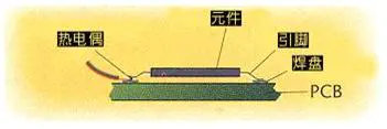
Light" (Front-Lighting) technology, as well as programmable lighting control, to better cope with a variety of different component placement needs. For example, simple components such as resistors and capacitors are illuminated from behind, and the vision system can reliably align them by simply recognizing the body outline. Conversely, dense-pin components such as QFPs* are better illuminated from the front, showing the complete distribution of pins around the package so that the vision system can reliably identify the alignment. Some BGAs have visible alignments on the bottom side of the component that can confuse the vision system, and these components require a side lighting system. It will illuminate the solder balls from the side instead of the alignment on the bottom side, so the vision system can check the solder ball distribution and correctly identify the component.
The highly** optical unit, flexible illumination and high resolution camera integrate the *optimal* image of the circuit and device, so that the feedback needed to correct board, component and feeder changes can be obtained by modern algorithms that are vital. Vision systems play an important role in successful placement equipment. By using advanced vision technology devices, higher levels of placement rates can be achieved. Defects occurring in pick-up are reduced, thus contributing to increased production on the entire production line and increased economic efficiency.
Vision systems are generally classified as overhead, elevation, head or laser aligned, depending on the location or type of camera.
(1) elevation camera is used to detect components in a fixed position, generally using CCD technology, before installation, the components must be moved over the camera in order to do visual alignment process. Roughly speaking, it seems to be a bit time-consuming. However, since the mounting head must be moved to the feeder to collect the components, if the camera is mounted between the pick-up position (from the feeder) and the mounting position (on the board), the vision acquisition and processing can be done simultaneously during the movement of the mounting head, thus shortening the mounting time.
(2) The overhead camera is mounted on the mounting head and is used to search for targets (called references) on the board in order to place the board in the correct position prior to placement.
(3) Laser alignment is to generate a moderate beam from a light source and shine it on the component to measure the impact of component projection. This method measures the size and shape of the component as well as the deviation of the center axis of the nozzle. This method is fast, because it does not require walking over the camera. However, its main drawback is that it can not pin and dense-pin components for pin inspection, for sheet components is a good choice. 90's laser alignment technology was introduced only to deal with 7´7mm components, the current ** generation of laser alignment system introduced by Anbion to deal with component size increased to 18´18mm, the laser technology can identify more shapes, the accuracy has also improved significantly.
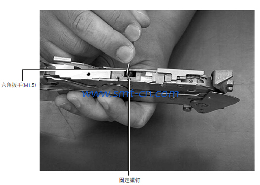
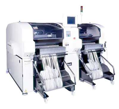
(4) the head camera is installed directly in the mount head, generally uses the line-sensor technology, in the process of picking up the component to move to the designated position to complete the detection of the component, this technology is also called "the flight alignment technology", it can greatly improve the mount efficiency. The system is composed of two modules: one module is the light source module composed of light source and lens. The light source adopts LED light-emitting diode and scattering lens, and the light source lens forms the light source module. Another module is accepting module, using LineCCD and a set of optical lens to form accepting module. These two modules are installed on both sides of the chip head spindle, with the spindle and other components to form the chip head, the chip machine has several chip head, there will be a corresponding set of several systems.
- Categories:Industry News
- Author:Becky Su
- Origin:
- Time of issue:2022-12-16 17:52
- Views:
Information
Vision Alignment System for Laminating Machine
The performance of CCD hardware currently used in chip machine lenses is of a comparable level. In the CCD hardware development earlier developed "Back-Lighting" (Back-Lighting) and "Front-Lighting" (Front-Lighting) technology and programmable lighting control to better cope with different component placement needs.
Light" (Front-Lighting) technology, as well as programmable lighting control, to better cope with a variety of different component placement needs. For example, simple components such as resistors and capacitors are illuminated from behind, and the vision system can reliably align them by simply recognizing the body outline. Conversely, dense-pin components such as QFPs* are better illuminated from the front, showing the complete distribution of pins around the package so that the vision system can reliably identify the alignment. Some BGAs have visible alignments on the bottom side of the component that can confuse the vision system, and these components require a side lighting system. It will illuminate the solder balls from the side instead of the alignment on the bottom side, so the vision system can check the solder ball distribution and correctly identify the component.
The highly** optical unit, flexible illumination and high resolution camera integrate the *optimal* image of the circuit and device, so that the feedback needed to correct board, component and feeder changes can be obtained by modern algorithms that are vital. Vision systems play an important role in successful placement equipment. By using advanced vision technology devices, higher levels of placement rates can be achieved. Defects occurring in pick-up are reduced, thus contributing to increased production on the entire production line and increased economic efficiency.
Vision systems are generally classified as overhead, elevation, head or laser aligned, depending on the location or type of camera.
(1) elevation camera is used to detect components in a fixed position, generally using CCD technology, before installation, the components must be moved over the camera in order to do visual alignment process. Roughly speaking, it seems to be a bit time-consuming. However, since the mounting head must be moved to the feeder to collect the components, if the camera is mounted between the pick-up position (from the feeder) and the mounting position (on the board), the vision acquisition and processing can be done simultaneously during the movement of the mounting head, thus shortening the mounting time.
(2) The overhead camera is mounted on the mounting head and is used to search for targets (called references) on the board in order to place the board in the correct position prior to placement.
(3) Laser alignment is to generate a moderate beam from a light source and shine it on the component to measure the impact of component projection. This method measures the size and shape of the component as well as the deviation of the center axis of the nozzle. This method is fast, because it does not require walking over the camera. However, its main drawback is that it can not pin and dense-pin components for pin inspection, for sheet components is a good choice. 90's laser alignment technology was introduced only to deal with 7´7mm components, the current ** generation of laser alignment system introduced by Anbion to deal with component size increased to 18´18mm, the laser technology can identify more shapes, the accuracy has also improved significantly.
(4) the head camera is installed directly in the mount head, generally uses the line-sensor technology, in the process of picking up the component to move to the designated position to complete the detection of the component, this technology is also called "the flight alignment technology", it can greatly improve the mount efficiency. The system is composed of two modules: one module is the light source module composed of light source and lens. The light source adopts LED light-emitting diode and scattering lens, and the light source lens forms the light source module. Another module is accepting module, using LineCCD and a set of optical lens to form accepting module. These two modules are installed on both sides of the chip head spindle, with the spindle and other components to form the chip head, the chip machine has several chip head, there will be a corresponding set of several systems.
Keyword:
Previous:
Instructions for buying reflow soldering
Next:
SMT equipment analysis
Previous:
Instructions for buying reflow soldering
Next:
SMT equipment analysis
Related News


PRODUCTS
CONTACT US
Hotline:(0086)755-27801389
Mobile: (0086)15323874439
Sale No.1: becky@hysmt.cn
Sale No.2: fhysmt@hysmt.cn
Sale No.3: zksale@hysmt.cn
Sale No.4: sale@hysmt.cn
Sale No.5: elsey@hysmt.cn
GIVE ME A MESSAGE
Copyright: ZK Electronic Technology Co., Ltd 粤ICP备11054297号 Powered by www.300.cn