Welcome to ZK Electronic

16 years of industry experience

Good material qualty, high efficiency, fast delivery

搜索

NEWS

NEWS

>
News
  • SMT mounter maintenance plan
    SMT mounter maintenance plan
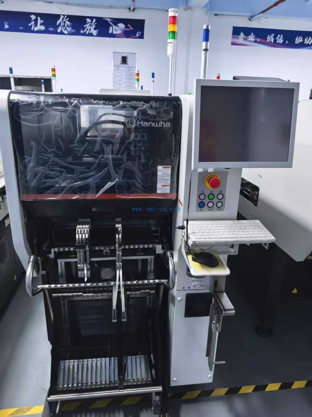
    SMT mounter maintenance plan SMT mounters should have a regular inspection and maintenance system.   1. Daily inspection (1)Before turning on the power of the mounting machine, check the following items. ① temperature and humidity: temperature between 20 ℃ ~ 26 ℃, humidity between 45 ~ 70%. ② Indoor environment: require clean air, no corrosive gas. ③Convinced that there is no debris on the transmission rail and within the moving range of the mounting head. ④Check that there is no debris on the fixed camera and that the lens is clean. ⑤ Make sure that there is no debris around the nozzle bank. ⑥Check that the nozzles are not dirty or deformed and clean or replace them. (vii) Check that the tape feeder is correctly positioned in the station and that there is no debris on the station. (8) Check the connection of the air connections, air hoses etc. (2) Check the following items after turning on the power to the labelling machine. If the machine is not operating correctly, an error message will be displayed on the monitor. (1) After booting the system, check that the menu screen is displayed properly. ② Press the "Servo" switch and the indicator light should be on. Otherwise, switch off the system, restart it and turn it on again. ③If the emergency switch is working properly. ④Check whether the mounting head can return to the starting point (source point) correctly. ⑤Check whether there is abnormal noise when the mounting head moves. ⑥Check that the negative pressure of the suction nozzle of all the mounting heads is within the measuring range. ⑦ Check that the PCB runs smoothly on the guide rails. Check whether the sensor is sensitive. ⑧Check whether the side positioning and needle positioning are correct. 2. Monthly check (1) Clean the screen of the CRT and the floppy disk drive (2) X and Y axes - make sure there is no abnormal noise in the X and Y axes when the attaching head is moving. (3) Cables - Ensure that there are no loose screws on the cables and cable brackets. (4) Air connectors - make sure that the air connectors are not loose. (5) Air hoses - Check the tubes and connections. Be satisfied that there are no leaks in the air hoses. (6) X and Y motors - Be sure that the X and Y motors are not abnormally hot. (7) Overtravel alarm - Move the attachment head in the positive and negative directions along the X and Y axes. When the mounting head is moved out of its normal range, an alarm should sound and the mounting head can stop moving immediately. After the alarm, use the manual operation menu to make sure the mounting head can operate. (8) Rotating motor - check that there is no dirt on the timing drive belt and gears. Ensure that the placement head can be rotated without obstruction. Ensure that the head has sufficient torque. (9) Z-axis motor - check that the placement head can move smoothly up and down. Push the nozzle upwards with your finger to see if it moves smoothly. Move the head up and down out of its normal range, check that the alarm sounds and that the head stops immediately. (10) S-motor (if there is a scanning CCD) one by one make sure that the scanning head moves smoothly. (11) Negative pressure - check the negative pressure of all placement heads. If the negative pressure value is not normal, clean the filter in the nozzle shaft and if the filter in the vacuum discharge tube is dirty (blackened), replace it. (12) Transfer guide - Check the movement of the transfer guide. Check the tightness of the conveyor belt. Check that the conveyor belt is free of stains, scratches and debris. Check the automatic width adjustment of the guide rails. Check movement when adjusted to *large and *small widths. Check the parallelism of the guide rails and the transfer of the PCB at the population and exit points. (13) PCB limiter - check its movement and noise. (14) Side clamping, rear top block, buffer block - check their wear. (15) Clamps on the nozzle bank - check for flexibility and wear. (16) Cameras - clean all camera lenses and light boxes. (17) Camera lighting unit - check its movement and brightness. (18) Operating switches - check that all brakes are working properly on the VO signal screen. Check the emergency stop switch. (19) Warning lights - Make sure all lights are illuminated. Make sure they are all securely mounted. (20) Danger alarms, warning alarms - check that they are working. (21) Camera - carry out a "picture check". (22) Pick-up point coordinates - check the pick-up point coordinates of the feeder station. (23) Placement position - make sure that the components can be assembled to the specified location. The SMT mounter maintenance schedule is described.
    2023-06-08
  • SMT component types
    SMT component types During the SMT production process, employees are exposed to more than a hundred different components and it is very useful to know them in order to work without or with less errors. Nowadays, with the spread of SMT technology, almost all kinds of electronic components are available in SMT packages. The most used electronic components in our company are resistors (R-resistor), capacitors (C-capacitor) (capacitors also include ceramic capacitors - C/C, tantalum capacitors - T/C, electrolytic capacitors - E/C), diodes (D-diode), voltage regulators diodes (ZD), triodes (Q-transistor), varistors (VR), inductive coils (L), transformers (T), transmitters (MIC), receivers (RX), integrated circuits (IC), speakers (SPK), crystal oscillators (XL), etc., which in SMT we can divide into the following categories: Resistors-RESISTOR Capacitors-CAPACITOR Diodes-DIODE Triodes-TRANSISTOR      Plugs-CONNECTOR Inductors-COIL Integrated blocks-IC Buttons-SWITCH etc. (a) Resistance 1. Unit: 1Ω=1×10⁻³ KΩ=1×10⁻⁶MΩ 2. Specifications: defined by the length and width of the component. There are 1005 (0402), 1608 (0603), 2012 (0805)          3216 (1206), etc. 3. The method of expression: 2R2=2.2Ω 1K5=1.5KΩ 2M5=2.5MΩ 103J=10×103Ω=10KΩ 1002F=100×102Ω=10KΩ (F, J refers to the error, F refers to ±1% precision resistance, J is ±5% of the ordinary resistance, F performance than the performance of J). Resistors are marked with numbers on top except 1005, which represents the capacity of the resistor. (ii) Capacitance: including ceramic capacitor - C/C, tantalum capacitor - T/C, electrolytic capacitor - E/C 1. Unit: 1PF = 1×10⁻³ NF = 1×10⁻⁶UF = 1×10⁻⁹MF = 1×10-12F   2. Specifications: defined by the length and width of the component, 1005 (0402), 1608 (0603), 2012 (0805)          3216 (1206), etc. 4. Tabular method:         103K=10×103PF=10NF 104Z=10×104PF=100NF 0R5=0.5PF    Note: electrolytic capacitors and tantalum capacitors are directional, white indicates the "+" pole. (iii) Diodes:      There are rectifier diodes, voltage regulator diodes and light emitting diodes. Diodes are directional and their positive and negative poles can be tested with a       Multimeter to test. (iv) Integrated blocks: (IC) There are SOP, SOJ, QFP, PLCC (v) Inductance: Unit: 1H = 103MH = 106UH = 109NH Expressed as: R68J=680NH 068J=68NH 101J=100UH 1R0=1UH 150K=15UH J and K refer to the error, the accuracy value is the same as the capacitor.
    2023-06-08
  • Compressed air for SMT
    Compressed air for SMT SMT compressed air requirements: clean and dry Dust particles, oil and liquid water in the air can be removed by relying on high efficiency filters. Many users only install simple oil and water separators at the inlet end of their SMT equipment. These have a very low filtration efficiency (typically no higher than 90%) and do not provide the level of gas purification required for SMT equipment use. The principles used for gas and liquid filtration are completely different, as the behavioural patterns of particles in air and liquid are quite different. Liquid filtration is mainly based on "blocking", while air filtration has three different principles: one is "direct capture" of larger, heavier particles that move in a straight line; the second is "inertial collision", which is used to capture slightly smaller, lighter particles that change direction slightly with the air flow; and very small particles are filtered out due to "Brownian motion". Once the particles hit the fibres, they are held firmly in place due to van der Waals forces, electrostatic suction and vacuum suction. Filters with high efficiency should be made of filter materials with good performance (e.g. borosilicate fibres) to provide clean air. At present, there are many filters designed and manufactured according to different filtering principles, and the following principles should be followed in the selection: (1) the level of the filter should be selected according to the situation of the compressed air source and the requirements for the use of the production equipment (e.g. the requirements of the equipment for the quality of compressed air, the pressure and flow of gas, etc.); (2) the filters of different levels should be followed in order from the low level to the highest level when used in combination configuration, can not jump levels at will} (3) filter element working life should be as long as possible, filter element replacement and maintenance should be convenient and simple; (4) the pressure drop between the filter inlet and outlet should be as small as possible; (5) the design of the filter should meet the requirements of ** production. Now, having a filter is not enough because, the water vapour in the air cannot be removed using a conventional filter and must be removed using a special drier. At present, there is a wide range of drying equipment for compressed air. Although the traditional adsorption dryer is cheap, it is bulky, the adsorbent is easy to age, consumes a lot of energy, and the regeneration of the adsorbent is more troublesome to deal with, and the filtering effect on water vapour is poor. Refrigerated dryer is a kind of compressed air drying equipment which is widely used* and *economical. Compared with other drying equipment, it does not consume any desiccant during operation and has the characteristics of energy consumption* saving and simple operation and maintenance*. SMT production equipment is generally required to be used in the plant where air conditioning is installed. In the hot and humid season, due to the large temperature difference between inside and outside the plant, the humid air is pressed into the network system by the air compressor without adding drying, and a large amount of water will condense in the process of temperature drop, while the water vapour remaining in the compressed air will directly enter the production equipment and continue to precipitate water in the process of further cooling, causing equipment damage. It is therefore essential that the air is dried before it enters the air-conditioned plant to filter out the water vapour contained in the air.
    2023-05-27
  • Electroplating process and role
    Electroplating process and role Acid dip: the main role is to remove the oxide layer on the board surface, to avoid water brought into the copper cylinder and affect the content of sulphuric acid. Cleaner: This cleaner is acidic and its main function is to remove fingerprints, grease and other residues from the surface of the board to keep it clean. Therefore, the grease, fingerprints should be prevented as a priority: and must pay attention to the compatibility of the resist layer and the matching between other fluids in the same line, and reduce the surface tension, the ability to exclude air bubbles in the hole. Micro-etching: As all kinds of dry film resist have additives to promote adhesion deep into the copper layer, 20~50u" of copper should be removed in this step to ensure a fresh copper layer to obtain good adhesion. Washing: The main function is to wash the residual solution from the board surface and the holes. Copper plating: The main components of the copper plating solution are copper sulphate, sulphuric acid, chloride ions, contaminants and other additives. Their respective roles are as follows: Copper sulphate: to provide the basic conductive copper ions required for plating to occur, the concentration is too high, although the operating current density can be slightly higher than the upper limit, but due to the concentration gradient difference is large, easy to cause Throwingpower**, and copper ions are too low, because the deposition rate is easily greater than the speed of diffusion movement, resulting in hydrogen ion reduction and the formation of scorching. Sulphuric acid: To provide a conductive acid ion to the bath. The ratio of sulphuric acid to copper is usually considered as "18g/l of copper metal + 180g/l of sulphuric acid" to maintain the acid to copper ratio above 10/1, 12:1 is better, ** not less than 6:1, high acid and low copper amount is prone to scorching, while low acid and high copper is not conducive to ThrowingPower. Chlorine ion: Its function is twofold, to help dissolve the anode properly and to help other additives to form a glossy effect, but too much chlorine ion will easily cause polarisation of the anode. Insufficient chloride ions can lead to abnormal consumption of other additives and imbalances in the bath (even fog deposition or step plating at very high levels; levelling** at too low levels). Other additives: The combined function of all other organic additives can achieve a regular crystalline arrangement of the lustre effect and improve the physical strength of the plating, while a relative excess of additives can easily cause the decomposition and oxidation of organic matter, pollution of the bath, increase in the frequency of activated carbon treatment, or an increase in the co-precipitation ratio of organic matter, resulting in increased internal stress and reduced ductility of the plating. Pollutants: Organic and inorganic pollutants can be distinguished, as the destruction of the equiaxial crystalline structure causes physical deterioration and co-precipitation causes deterioration in appearance. The sources of organic contamination are: oxidative decomposition of lustre agents, inks, dry films, baths, filters, anode bags, hanger cladding films and other filtered out substances and environmental pollutants. The sources of inorganic pollution are: environmental pollution, water pollution and basic material pollution.
    2023-05-27
  • SMT process flow and process description
    SMT process flow and process description 一, chip components single-side mount process 1. Incoming material inspection Description: Check whether the components, pads, solder paste have oxidation, whether the solder composition matches, integrated circuit pins and its coplanarity. 2. Printing solder paste Description:Through solder paste printing machine or SMT solder paste printing table, printing special scraper and SMT leakage board will SMT solder paste leakage printing to the PCB pads. 3. Check the printing effect Description: Check whether the printed circuit board solder paste leakage, adhesion, the amount of solder paste is appropriate, etc. 4.SMD Description:Finish the placement by the placement machine or vacuum suction pen, tweezers, etc. 5. Check SMT placement effect Description: Check whether the posted components are put on the deviation, put on the reverse or leak, and repair, narrow pitch components need to use microscope entity check. 6. Check reflow soldering process setting Description: Check the working conditions of reflow soldering, such as power supply voltage, temperature curve setting, etc. 7. Reflow soldering Description: Reflow soldering by SMT reflow equipment. 8. Check the welding effect and *final inspection Description: Check whether there are welding defects and repair. 二, chip components double-sided placement process 1.Incoming material inspection 2.Screen printing A side solder paste 3. Check the printing effect 4. Mount A-side components, check the effect of SMD 5.Reflow soldering 6.Check the soldering effect 7. Print B-side solder paste 8.Check the printing effect 9. Mount B-side components, check the effect of patching 10.Reflow soldering 11.Repair check 12.* Final inspection Attention matters: 1: A, B side of the distinction is the circuit board in components less and small for A side, components more and large for B side. 2: If both sides have large package components, you need to use a different melting point of the solder paste. That is: A side with high temperature solder paste, B side with low temperature solder paste 3: If there is no different temperature of the solder paste, you need to add a step, that is, after the completion of step 7, you need to A side of the large package components        With SMD red glue sticky, and then the B side of the operation. 4: Other steps operation with process (a) 三, research and development in the mixed board placement process 1. incoming material check Description: check whether the components, pads, solder paste have oxidation, whether the solder composition matches, integrated circuit pins and its coplanarity. 2. Drop coating solder paste Description: Use SMT solder paste dispenser, air compressor to drop coating the solder paste in SMT syringe to PCB pads. 3. Check the effect of drip coating Explanation: Check whether the amount of solder paste drip coated is suitable, whether there is leakage of coating or sticking. 4. Placement of components Description:Finished by vacuum suction pen or tweezers, etc. 5. Check the effect of SMD Description: Check whether the pasted components are put on the wrong side, put on the opposite or leak, and repair. 6. Reflow soldering Description: Reflow soldering by HT series desktop small SMT reflow soldering equipment. 7. Check the welding effect Description: Check whether there are welding defects and repair. 8. Solder the plug-in parts Description:Finished by electric soldering iron, solder wire and flux with. 四, double-sided mixed batch production placement process 1.Incoming material check 2. Screen printing A side solder paste 3. Check the printing effect 4. Mount A-side components 5.Check the effect of mounting 6.Reflow soldering 7.Check the soldering effect 8.Printing B-side red glue 9.Check the printing effect 10.Placement of B-side components 11.Check the effect of placement 12.Curing 13.Insert THT components on A side 14.Check the effect of insertion 15.Wave soldering 16.Repair solder joint cleaning test Description: Caution and operation process as described above.
    2023-05-16
Previous
1
2
...
15

CONTACT US

Hotline:(0086)755-27801389
Mobile: (0086)15323874439
Sale No.1: becky@hysmt.cn
Sale No.2: fhysmt@hysmt.cn
Sale No.3: zksale@hysmt.cn
Sale No.4: sale@hysmt.cn
Sale No.5: elsey@hysmt.cn

GIVE ME A MESSAGE

Copyright: ZK Electronic Technology Co., Ltd    粤ICP备11054297号    Powered by www.300.cn