Welcome to ZK Electronic
16 years of industry experience
Good material qualty, high efficiency, fast delivery
搜索
NEWS
Evaluation of a placement machine vision system for SMD placement alignment
- Categories:Industry News
- Author:Becky Su
- Origin:
- Time of issue:2022-12-20 14:30
- Views:
(Summary description)Evaluation of a placement machine vision system for SMD placement alignment I. Support for multiple types of cameras Previously the time to process images has always been longer than the time to acquire them, but new developments in CPU technology have accelerated image processing, and image acquisition speed may instead become a limiting factor. In order to improve system processing efficiency, to reduce the time to acquire images to a * low degree, the vision system should be able to support a variety of advanced line scan, high resolution (1024 × 1024 pixels), high-speed digital cameras. Second, identify non-standard device capability Machine vision systems should be able to reliably identify the shape of various non-standard devices, regardless of how rare they are. The existing patch alignment software, with built-in geometric pattern finding tools, these tools can "learn" the geometric properties of the device, even if it is oddly shaped, the system can identify the device. Three, the ability to reliably avoid the nozzle SMD component placement generally uses either front lighting or backlighting, or both. Backlighting is used to produce a back image of the device, revealing an image similar to a binary image, making it easier for the vision system to identify the device, and this type of lighting is often used when identifying simple devices such as chip resistive capacitors. However, backlighting can also pose a problem for the vision system: the back image of the pickup device's nozzle often protrudes from the back of the device or partially obscures the chip (e.g., Figure 10). While frontal illumination techniques can prevent this phenomenon, the pixel grayscale values of the nozzle itself may prevent the vision system from reliably distinguishing between the nozzle and the device. Choosing a vision system that can recognize the difference in shape between the device and the pick-up device's nozzle, such a system can tolerate partial masking of the nozzle and therefore will improve device alignment accuracy and prevent devices from being misplaced due to visual errors. IV. Ability to identify closely spaced devices and white ceramic surface devices In order to **identify various devices such as BGAs, flip-chips or CSPs, and to check for pin deviations, the vision system should reliably identify white ceramic surface devices, whose low-contrast reflective nature would render conventional vision techniques useless. The vision system must also be able to accurately locate each component. These functions should be verified, and the test software should be able to distinguish between individual objects. V. Ability to automate programming For very special components, new vision software tools should have the ability to automatically "learn", the user does not have to manually input parameters into the system to create a device description from scratch, they just need to take a picture of the device to the vision camera can be, the system will automatically produce a comprehensive description similar to CAD. This technology can improve the accuracy of device descriptions and reduce many operator errors, speed up the creation of component libraries, especially in the case of frequent introduction of new devices or the use of uniquely shaped devices, thereby improving production efficiency. Six, the ability to reliably determine the location of the PCB reference mark Since reliable positioning of PCB reference marks is the **step** to any SMD placement alignment, the vision system must be able to identify different references, even in conditions where the appearance of the reference is not ideal. For example, variations in oxidation, tinning, and wave solder from the manufacturing process can cause specular reflections and surface inconsistencies that can dramatically change the appearance of the marker. Other factors that may affect the appearance of the reference include board distortion, excessive solder buildup, board color changes, and more. A vision system that tolerates these conditions can help users improve alignment success and reduce operator intervention. Taking these factors into account ensures that you can easily handle new component types and different devices from different manufacturers, and that the system you choose is highly flexible, making the user's job easier.
Evaluation of a placement machine vision system for SMD placement alignment
(Summary description)Evaluation of a placement machine vision system for SMD placement alignment
I. Support for multiple types of cameras
Previously the time to process images has always been longer than the time to acquire them, but new developments in CPU technology have accelerated image processing, and image acquisition speed may instead become a limiting factor. In order to improve system processing efficiency, to reduce the time to acquire images to a * low degree, the vision system should be able to support a variety of advanced line scan, high resolution (1024 × 1024 pixels), high-speed digital cameras.
Second, identify non-standard device capability
Machine vision systems should be able to reliably identify the shape of various non-standard devices, regardless of how rare they are. The existing patch alignment software, with built-in geometric pattern finding tools, these tools can "learn" the geometric properties of the device, even if it is oddly shaped, the system can identify the device.
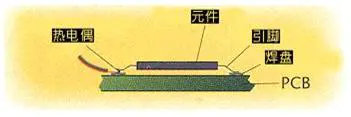
Three, the ability to reliably avoid the nozzle
SMD component placement generally uses either front lighting or backlighting, or both. Backlighting is used to produce a back image of the device, revealing an image similar to a binary image, making it easier for the vision system to identify the device, and this type of lighting is often used when identifying simple devices such as chip resistive capacitors. However, backlighting can also pose a problem for the vision system: the back image of the pickup device's nozzle often protrudes from the back of the device or partially obscures the chip (e.g., Figure 10). While frontal illumination techniques can prevent this phenomenon, the pixel grayscale values of the nozzle itself may prevent the vision system from reliably distinguishing between the nozzle and the device. Choosing a vision system that can recognize the difference in shape between the device and the pick-up device's nozzle, such a system can tolerate partial masking of the nozzle and therefore will improve device alignment accuracy and prevent devices from being misplaced due to visual errors.
IV. Ability to identify closely spaced devices and white ceramic surface devices
In order to **identify various devices such as BGAs, flip-chips or CSPs, and to check for pin deviations, the vision system should reliably identify white ceramic surface devices, whose low-contrast reflective nature would render conventional vision techniques useless. The vision system must also be able to accurately locate each component. These functions should be verified, and the test software should be able to distinguish between individual objects.
V. Ability to automate programming
For very special components, new vision software tools should have the ability to automatically "learn", the user does not have to manually input parameters into the system to create a device description from scratch, they just need to take a picture of the device to the vision camera can be, the system will automatically produce a comprehensive description similar to CAD. This technology can improve the accuracy of device descriptions and reduce many operator errors, speed up the creation of component libraries, especially in the case of frequent introduction of new devices or the use of uniquely shaped devices, thereby improving production efficiency.
Six, the ability to reliably determine the location of the PCB reference mark
Since reliable positioning of PCB reference marks is the **step** to any SMD placement alignment, the vision system must be able to identify different references, even in conditions where the appearance of the reference is not ideal. For example, variations in oxidation, tinning, and wave solder from the manufacturing process can cause specular reflections and surface inconsistencies that can dramatically change the appearance of the marker. Other factors that may affect the appearance of the reference include board distortion, excessive solder buildup, board color changes, and more. A vision system that tolerates these conditions can help users improve alignment success and reduce operator intervention.
Taking these factors into account ensures that you can easily handle new component types and different devices from different manufacturers, and that the system you choose is highly flexible, making the user's job easier.
- Categories:Industry News
- Author:Becky Su
- Origin:
- Time of issue:2022-12-20 14:30
- Views:
Information
Evaluation of a placement machine vision system for SMD placement alignment
I. Support for multiple types of cameras
Previously the time to process images has always been longer than the time to acquire them, but new developments in CPU technology have accelerated image processing, and image acquisition speed may instead become a limiting factor. In order to improve system processing efficiency, to reduce the time to acquire images to a * low degree, the vision system should be able to support a variety of advanced line scan, high resolution (1024 × 1024 pixels), high-speed digital cameras.
Second, identify non-standard device capability
Machine vision systems should be able to reliably identify the shape of various non-standard devices, regardless of how rare they are. The existing patch alignment software, with built-in geometric pattern finding tools, these tools can "learn" the geometric properties of the device, even if it is oddly shaped, the system can identify the device.
Three, the ability to reliably avoid the nozzle
SMD component placement generally uses either front lighting or backlighting, or both. Backlighting is used to produce a back image of the device, revealing an image similar to a binary image, making it easier for the vision system to identify the device, and this type of lighting is often used when identifying simple devices such as chip resistive capacitors. However, backlighting can also pose a problem for the vision system: the back image of the pickup device's nozzle often protrudes from the back of the device or partially obscures the chip (e.g., Figure 10). While frontal illumination techniques can prevent this phenomenon, the pixel grayscale values of the nozzle itself may prevent the vision system from reliably distinguishing between the nozzle and the device. Choosing a vision system that can recognize the difference in shape between the device and the pick-up device's nozzle, such a system can tolerate partial masking of the nozzle and therefore will improve device alignment accuracy and prevent devices from being misplaced due to visual errors.
IV. Ability to identify closely spaced devices and white ceramic surface devices
In order to **identify various devices such as BGAs, flip-chips or CSPs, and to check for pin deviations, the vision system should reliably identify white ceramic surface devices, whose low-contrast reflective nature would render conventional vision techniques useless. The vision system must also be able to accurately locate each component. These functions should be verified, and the test software should be able to distinguish between individual objects.
V. Ability to automate programming
For very special components, new vision software tools should have the ability to automatically "learn", the user does not have to manually input parameters into the system to create a device description from scratch, they just need to take a picture of the device to the vision camera can be, the system will automatically produce a comprehensive description similar to CAD. This technology can improve the accuracy of device descriptions and reduce many operator errors, speed up the creation of component libraries, especially in the case of frequent introduction of new devices or the use of uniquely shaped devices, thereby improving production efficiency.
Six, the ability to reliably determine the location of the PCB reference mark
Since reliable positioning of PCB reference marks is the **step** to any SMD placement alignment, the vision system must be able to identify different references, even in conditions where the appearance of the reference is not ideal. For example, variations in oxidation, tinning, and wave solder from the manufacturing process can cause specular reflections and surface inconsistencies that can dramatically change the appearance of the marker. Other factors that may affect the appearance of the reference include board distortion, excessive solder buildup, board color changes, and more. A vision system that tolerates these conditions can help users improve alignment success and reduce operator intervention.
Taking these factors into account ensures that you can easily handle new component types and different devices from different manufacturers, and that the system you choose is highly flexible, making the user's job easier.
Keyword:
Previous:
What to learn in the SMT industry
Previous:
What to learn in the SMT industry
Related News


PRODUCTS
CONTACT US
Hotline:(0086)755-27801389
Mobile: (0086)15323874439
Sale No.1: becky@hysmt.cn
Sale No.2: fhysmt@hysmt.cn
Sale No.3: zksale@hysmt.cn
Sale No.4: sale@hysmt.cn
Sale No.5: elsey@hysmt.cn
GIVE ME A MESSAGE
Copyright: ZK Electronic Technology Co., Ltd 粤ICP备11054297号 Powered by www.300.cn